Best Price on Spiral Wound Gasket-CG to Iceland Factories
Best Price on Spiral Wound Gasket-CG to Iceland Factories Detail:
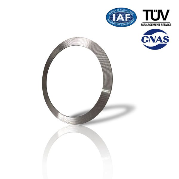
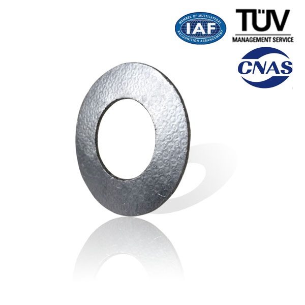
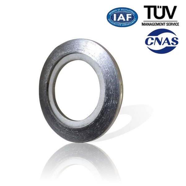
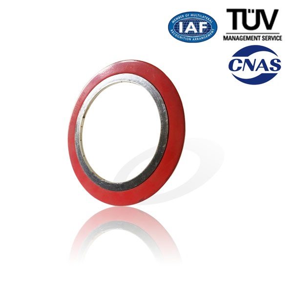
Spiral wound gasket consists of “V-shape”(or”W-shape”)metal tape and nonmetal tape, which are overlapped each other and wound continuously.To fasten the metal tape,both its start point and end point are tack welded.
Feature
Wide Scope of acceptable working conditions. Can be used under high temperature, high pressure and ultra-low temperature or vacuum conditions. Change the combination of the gasket materials is to tackle the chemical corrosion problem of diverse media toward the gasket.
Not very rigid requirements to the surface precision of the flange. May be used to seal flanges with rough surface
Easy installation and handy use.
Excellent Sealability
Products Type
Technical Data Sheet
|
Product&Type |
Size(mm) |
Temperature(℃) |
Pressure(Mpa) |
|
Spiral Wound Gasket filled with Graphite
|
φ16~φ3200 |
(In Oxidizing Environment )-240~+550℃;(In non-Oxidizing Environment)-240~+870℃ |
(Under hot water, oil etc. )30 Mpa; (Under vapor oil, gases etc.)20 Mpa |
|
Spiral Wound Gasket filled with Asbestos
|
φ16~φ3200 |
-150~+450℃ |
15 |
|
Spiral Wound Gasket filled with Asbestos
|
φ16~φ3200 |
-150~+450℃ |
15 |
|
Spiral Wound Gasket filled with PTFE
|
φ16~φ3200 |
-200~+250℃ |
15 |
Application Area
The Spiral Wound Gaskets are mainly used in valves &pipes, pressure vessel, condenser, heat exchanger flanges in oil, chemical, metallurgy, vessel and mechanical industries.
Product detail pictures:
Related Product Guide:
A Look at the Molded Gasket
O-Ring Sizes for Industrial Applications
Best Price on Spiral Wound Gasket-CG to Iceland Factories, The product will supply to all over the world, such as: , , ,
The Types 3271 and 3277 Pneumatic Actuators contain a rolling diaphragm and internal springs.
Special features
• Low overall height
• Powerful thrust at high response speed
• Low friction
• Various bench ranges by varying the number of springs or their compression
• No special tools required to change the bench range and to reverse the actuator action (also version with handwheel)
• Permissible operating temperatures from –50 to +120 °C
• Direct attachment of accessories on additional yoke for
• Type 3277 with concealed travel pick-off
Samson 3241 Globe Control Valve
The control valves consist of a body with trim, bonnet and pneumatic actuator, optionally with metal bellows or insulating extension. The valves may be also equipped with electric, electro-hydraulic, or hand-operated actuators, as well as control accessories and other instrumentation.
Application
Control valve for process engineering and plants with industrial requirements.
Nominal valve sizes 1⁄2” to 10” (15 to 250 mm) Pressure ratings ANSI Class 125 to 300
Temperatures −320 °F to +800 °F (−196 °C to +427 °C)
Features
• Modular design, rugged and heavy duty construction, full range of body and trim materials
• One-piece ultra-rigid valve bonnet and yoke up to size 6”
• Field retrofittable extension bonnets and metal bellows seals
• Many configurations, e.g. Cryogenic or ‘Lethal service’
• Self-adjusting, live-loaded PTFE V-ring stuffing box
• Port-guided V-port asymetric plugs above CV 20 standard
• Excellent dynamic response and high trim stability
• Self-locking seats, exchangeable for various CV values
• Low height, reversible, multi-spring/rolling diaphragm actuator
• NAMUR (IEC 534-6) accessory mounting standard
• Complete selection of actuators options, positioners and control accessories
Installing a SAMSON 3277 Actuator to a 2″ Samson 3241 Globe Control Valve
In this video, we’ll describe how to install a SAMSON 3277 actuator to a 2″ 3241 globe valve. The actuator in this example fails closed and is a size 350cm with a 3-15psi spring range.
Step by Step Instructions:
1. Begin by carefully placing the actuator onto the valve bonnet to avoid thread damage.
2. For this example we’re using a 3-15 psi actuator, apply approximately 20psi to retract the stem. This allows us to install the ring nut without causing any damage to the plug and seat sealing surfaces. Thread on the ring nut and lock into position.
3. To set the bench range, apply a pressure equal to the lower bench range; 3 psi in our case.
4. Push down on the plug to make sure it’s firmly pressed into the seat. Raise the stem connector nut until it makes contact with the actuator stem and add an additional ¼ turn. Then, raise the lock nut and secure into position with two wrenches.
5. The stem connector clamp is now installed to mechanically link the actuator stem to the plug.
6. If necessary, adjust the travel indicator to the correct position.
7. Actuator installation is now complete.
RENCOR Controls
21 Sullivan Parkway
Fort Edward, NY 12828
Phone: (800) 777- 4174
Fax: (518)747- 4176
www.rencor.com
rencor@rencor.com


