Factory Free sample Spiral Wound Gasket-CG for Boston Factories
Factory Free sample Spiral Wound Gasket-CG for Boston Factories Detail:
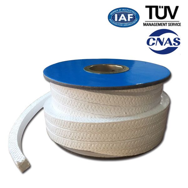
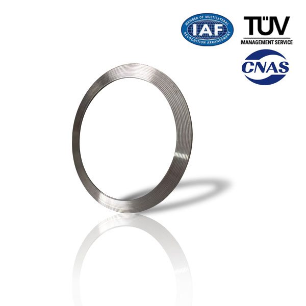
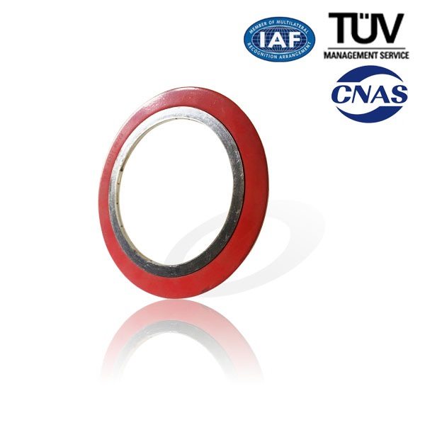
Spiral wound gasket consists of “V-shape”(or”W-shape”)metal tape and nonmetal tape, which are overlapped each other and wound continuously.To fasten the metal tape,both its start point and end point are tack welded.
Feature
Wide Scope of acceptable working conditions. Can be used under high temperature, high pressure and ultra-low temperature or vacuum conditions. Change the combination of the gasket materials is to tackle the chemical corrosion problem of diverse media toward the gasket.
Not very rigid requirements to the surface precision of the flange. May be used to seal flanges with rough surface
Easy installation and handy use.
Excellent Sealability
Products Type
Technical Data Sheet
|
Product&Type |
Size(mm) |
Temperature(℃) |
Pressure(Mpa) |
|
Spiral Wound Gasket filled with Graphite
|
φ16~φ3200 |
(In Oxidizing Environment )-240~+550℃;(In non-Oxidizing Environment)-240~+870℃ |
(Under hot water, oil etc. )30 Mpa; (Under vapor oil, gases etc.)20 Mpa |
|
Spiral Wound Gasket filled with Asbestos
|
φ16~φ3200 |
-150~+450℃ |
15 |
|
Spiral Wound Gasket filled with Asbestos
|
φ16~φ3200 |
-150~+450℃ |
15 |
|
Spiral Wound Gasket filled with PTFE
|
φ16~φ3200 |
-200~+250℃ |
15 |
Application Area
The Spiral Wound Gaskets are mainly used in valves &pipes, pressure vessel, condenser, heat exchanger flanges in oil, chemical, metallurgy, vessel and mechanical industries.
Product detail pictures:
Related Product Guide:
O-Ring Sizes for Industrial Applications
A Look at the Molded Gasket
Factory Free sample Spiral Wound Gasket-CG for Boston Factories, The product will supply to all over the world, such as: , , ,
PARTS LIST BELOW. Got this idea from u-tuber Approtechie. He has a lot of good ideas. Use schedule 40 white PVC pipe. I don’t have back up power here so this is my way of accessing my most convenient source of clean water if the power should go out for a long period of time. I used teflon tape on any threaded joints(probably not necessary). This cost about $70 to put together. It looks like from comments that pumping from water levels deeper than 50ft is a very heavy lift. So maybe not worth going deeper. Maybe Approtechie has an opinion on that considering he designed these himself. My only experience is with my own well which has a pretty shallow static water depth of about 11ft., pretty easy at that depth.
Parts List
Outer Pipe Assembly-
-One 11/4″ plastic foot valve(Lowes has them)
-One 11/4″ adapter(slip x thread)
-As much 11/4″ PVC pipe and couplings as needed
-One 11/4″ x 1″ Tee(slip)- This is at the top.
-One 11/4″ x 1″ Bushing(slip)- This goes into the tee.
-One 1″ x 1/2″ Bushing(slip) Trim the inside of this one.- This goes into the previous bushing.
Inner Pipe Assembly-
One 3/4″ Plastic foot valve
-One 3/4″ Adapter(slip x thread) Trim the nubs off of this one.
-One 3″ length of 3/4″ pipe. Sand one end to fit into 1″ piston pipe.- Connects the piston to the adapter.
-About a 3ft. length of 1″ pipe- this will be the piston.
-One more 1″ x 1/2″ Bushing(slip). Don’t trim this one. Glue it to the top of the piston and glue the 1/2″ ram pipe to it.
-As much 1/2″ pipe and couplings as needed(drill 1/4″ holes straight through this pipe just above the piston).
-One 1/2″Tee(slip) + two short lengths of 1/2″ pipe with two 1/2″caps(slip) complete the handle at the top of the 1/2″ ram pipe.
THAT’S IT….But for this design to work ,as seen, you MUST SEAL UP THE 1/2″ pipe so that water doesn’t go up it too much higher than the 1/4″ transfer holes. Certainly not all the way to the top(check out the Further Pump Explanation vid in this box).
I capped the handle off completely in order to trap air inside the upper portion of the 1/2″ pipe so that I don’t waste energy lifting a lot of trapped water up and down. But mostly because it forces the water out the 11/4Tee which is where I want it to go. Otherwise it could come out the handle as well which I do not want. You could, instead of capping the handle off, block up the 1/2″ pipe just above the transfer holes by gluing a nickel into one of the 1/2″ couplings. This would accomplish the same thing and make the caps on the Tee unnecessary. It would also allow you to install the 1/2″ pipe one piece at a time, if you wanted to, without it filling up with water. I was a little worried that the trapped air in my pump would make the inner pipe too buoyant and rise up on its own so I drilled a hole in it about midway down to add a little weight. My well is pretty clean so I didn’t put any kind of filter at the bottom. Some wells might need a finer screen than the one that comes with the foot valve( I think I’ve heard of people using sack cloth for this but not sure). For larger depths it might help to make the piston longer, maybe 5ft.
Youtuber sameggers1 did a great video of his deep well version
https://youtu.be/pXBRVi0eMvA
Here is Approtechie’s video, a must see.
https://youtu.be/OdVw5R4JBfc
My vid.-Further Pump Explanation https://youtu.be/XjGUdxSgosQ


